roofing and fascia

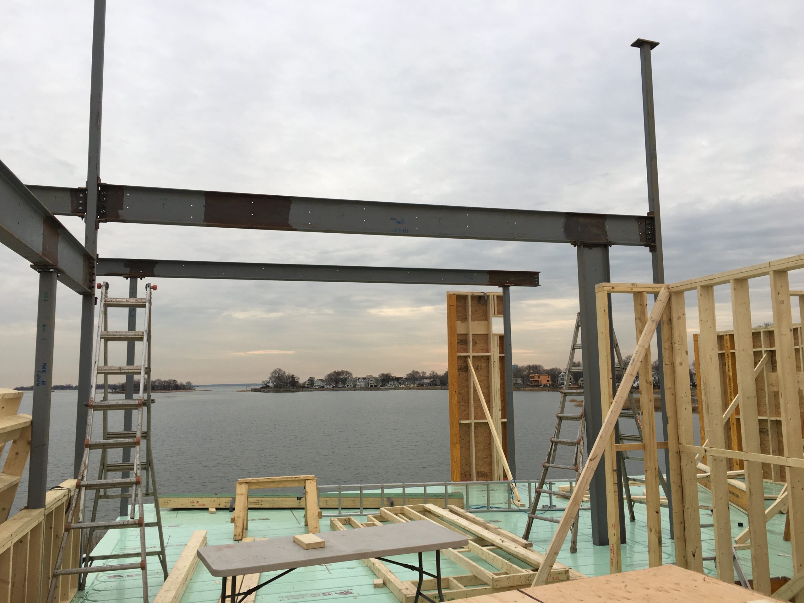
As soon as the shell of the home was complete we got moving on getting the roofing completed, in parallel with installation of the windows. There were/are four roof surfaces, the top surface pitched 1″ per 12″, and the other surfaces were all flat with plans calling for tapered foam to bring to 1/4″ per 12″.

The top roof was sufficiently pitched for a metal roof, and given the salt air environment we opted for an aluminum standing seam roof. Our roofing contractor used coil from Englert and we picked Dove Gray for the Kynar coating (I think we used 0.032″ aluminum). At this point we had pretty much settled on using Cembonit (now called Patina) in their pearl color for the siding, with a couple of accent walls in Trespa Pura in their romantic walnut, with lower level and trim (and windows) in a bronze color.

For the flat roof surfaces we looked into monolithic (liquid applied) membranes, which are pretty cool, but cost was 2-3x the cost for EPDM. Liquid membranes we looked at included Soprema Alsan RS and Kemper. Our (local) roofer, who was one of our best subs, said he had some experience with these, but for residential construction I think these are a pretty esoteric choice. Our concern with EPDM, which turned out to be misplaced, was rubber tire smell when the roof got hot, and to a lesser extent longevity/durability. It really did not smell, even when new. There are liquid coatings that can be applied to EPDM to increase reflectivity and longevity, we could still put one of these down at some point.

For roof and overhang fascia the plans called for 1x Azek trim painted (it only comes in flat white color) to match window trim (so for us a dark bronze color). The idea of having to repaint trim was not at all attractive to us, 30-odd feet up in the air. Our goal with all exterior material selections was to pick things that were low or no maintenance. I rebuilt a deck at our last house and used TimberTech full PVC boards and fascia. TimberTech has since been acquired by Azek and their boards are capped, but they still make and sell colored PVC fascia boards that are 0.5″x11.75″x12′. The boards are expensive at a little over $100 per, but the Azek warranty is impressive and the color (we picked cypress) is hanging in there 3 or so years in. The roofing crew put the fascia up and found the rim and outer joists to not be very fair, so there was a lot of shimming to get the fascia to be straight.

There are special colored fasteners for the fascia and also a bit for pre-drilling/countersinking that creates a hole that is a bit larger than the screw to allow for movement (PVC moves a lot with temperature). The crew did not really follow the instructions and fixed the fascia without allowing for movement in many places. So far it is holding up.

Metal roof underlayment complete, fascia starting to go up, lots of shimming …
Aluminum coil for roof in truck, formed into panels on site
Aluminum standing seam installation in process
Tapered foam out on the roof ready for installation, to create 1/4″ in 12″ pitch for water runoff, and extra R as a bonus!

The crew flashed the roof/wall connections with copper, not sure exactly what this does, but I think they knew what they were doing. That said, this joint was problematic in a couple of spots where the EPDM was brought up the side of the Zip system sheathing, creating a reverse lap that for me is a fatal flaw of this approach. More on this in another post, but we had leaking problems at this joint and we ended up wrapping the entire home using VaproShield’s RevealShield SA, making the Zip sheathing sort of a waste of time and money. The Zip panels are also OSB, which for strength is inferior to plywood. Lesson learned, for me plywood sheathing and a high quality wrap/vapor barrier are the way to go.

Leaky roof/wall joint
Roofing complete, EPDM drip edge in same aluminum material and color used for the main roof
Completed home showing the colors we chose, siding is Pearl Cembonit, corner of the main floor is wrapped in Romantic Walnut Trespa Pura, fascia is Azek in Cypress, main roof and EPDM drip edge is Englert Dove Gray, window trim and garage doors and lower level corrugated aluminum is dark bronze, decks are Cumaru with stainless cable rails, exterior stairs galvanized steel

The metal roof can be quite noisy on hot, windy summer days. Not sure if this is because of an installation problem, or if it is just a metal roof thing. But it is loud enough that it is a little annoying. Also if we get a melt and then a freeze you can get some pretty hefty ice slabs that eventually get cut by the seams and then slide off onto the roof below, with a large bang. Given that the roof below is EPDM over rigid foam the makes me worry about getting a puncture, so when these conditions occur I go up to manage the movement of ice from upper to lower roof. I am not sure if there is a better way or not. Our neighbor has some snow guards on his standing seam roof, perhaps we should look into putting some of those up. There are also some little stick on shark fins that supposedly slice the ice into smaller chunks.

window configuration, selection, and installation

As we went through the process of developing the construction drawings with Turkel we made some changes to window sizes and locations to (a) improve potential airflow through the home, (b) improve privacy, and (c) accommodate limitations of another product line we decided to include in the package. Once the windows were on site and they started to go in we learned about implications of some decisions we had made without knowing we had made the decisions.

In the initial design all three bedrooms had operating windows on only one wall (the master had a tall/skinny window around the corner of the main wall of windows). That did not make sense to us, and the next iteration had two windows either side and adjacent to a corner of one bedroom. The discussion with Turkel was about airflow you get when you blow on a straw while you have your thumb over the other end of the straw. So we added some operating windows and tried to get them on opposite sides of the rooms.

The home is on the water and SSE facing, and most of the south and east sides of the home are glass. The prevailing breeze in the summer is SW, and initially there was no nice way to open up the north side of the home without propping the front door open. So we added some windows to the north side, including a large operating casement adjacent to the front door (more on the front door in another post). We also added a high window to the powder room, over the commode in the master (giving windows on two walls of the master bath, up high for privacy, but adding natural light and operable for airflow), and a couple of small high windows in the mechanical room.

The Marvin Ultimate window package was not an insignificant cost that was not broken out in the Turkel purchase order, and we tried to get some visibility into that cost as we looked at making changes to the window package. This process was slow and difficult, so we started talking to other suppliers to try to get some cost granularity. During those efforts a couple of suppliers suggested that (Marvin) Integrity windows might outperform Marvin Ultimates and also save some money. Ultrex windows are strong, resulting in small rails and so larger openings, and are not susceptible to corrosion, so ideal for water front homes. Turkel had limited experience with this line of windows and it was a process to bring them up to speed of what was possible and what was not possible. Fixed Integrity casements are available in sizes up to 49 sqft, which is about as large a window as I’d want to have. The size of Integrity awnings is limited compared to Ultimates, so under large windows we doubled up Integrity awnings (so more smaller operable windows, which was fine with us and has worked well in practice), and for large awnings and a multi-slide assembly we stayed with Marvin Ultimates. The Integrity were available with wood on the interior, as well as Ultrex (we used the latter for bathrooms and laundry and mechanical rooms). All windows were available with square sticking and the exterior bronze color of Ultimate and Integrity windows is VERY close. I think more factory mulling gets done with the Ultimate windows, for our Integrity windows steel was installed for at least some of the mulling (maybe partially negating some of the cost savings, but again in a salt air environment I think I pick Ultrex over Kynar coated aluminum). The Marvin Ultimate hardware is a little nicer than the Integrity, but the Integrity is still quite OK and you would not really notice much of a difference unless it was side by side. The awning control handles are both metal, but on the Integrity the locking levers look like they are metal but they are plastic (on the all Ultrex they are white plastic).

Largest window in the house on right in master suite, pretty close to 7’x7′, steel bar to mull upper units to lower awning assemblies
1″ steel plates used for mulling, awnings below large fixed casements for airflow
Full Ultrex Integrity windows in guest bath
Wood/Ultrex Integrity windows and door
Multi slide assembly
Two Marvin Ultimate awnings on the left, Integrity fixed casements/polygons to the right
Integrity on the left, Marvin Ultimate on the right, bronze colors quite a close match

On the stuff we learned about after the windows were on site, that was around jamb extensions and how the window frames were placed in the rough openings. Here is where we started to learn how finishing details could have huge cost implications. For the interior window to wall transitions the plans called for two pieces of trim, one of which was dadoed with the drywall going into the dado. Clearly a ton of work and our construction manager was puzzled by the design. If we were going to bring a jamb extension past the drywall I did not understand why we did not just have jamb extensions built into the windows by Marvin, then bring the drywall up pretty tight and use tear away beads to finish, that would have been a lot less work. The typical finish would be to install a jamb extension bringing the jamb flush with the drywall and then banging some casing around the window. None of these approaches seemed to be very clean to me, clean and minimal was a core tenet of the whole project. So we ended up using drywall for the “jamb extension,” using a tear away bead for finishing at the window jamb and a corner bead at the drywall to drywall corner (much as you would handle the outside corner of a wall). Still a lot of work (and cost), but a much cleaner look.

Window to wall transitions
Drywall jamb extensions, tear away beads at window jambs, corner beads at wall corners

After the windows were in we learned about the importance of how those are placed in the rough openings. The plans called for 1×3 furring of all exterior soffits and interior ceilings. Our construction manager thought it was a waste of time and money to add furring to all of the joists for the ceilings, and installing furring on all of the (pretty extensive) soffits was not going to be cheap. If you did one and not the other the interior to exterior transitions at the windows would have a 3/4″ step from the side with furring to the side without. We decided to skip the furring and deal with gaps that might require trim on the exterior.

During the development of the construction drawings we had been discussing cladding options. On the lower level our thought was to have corrugated break-away aluminum panels between the concrete piers, and we had the idea to bring this aluminum up at a corner of the house to provide an accent to the main cladding (Cembonit cement board panels, more on that in another post). What I did not realize was that as a result of floating the idea of the corrugated aluminum we signed up for 2×4 furring for the cement board rain screen siding. So windows were installed with frames sticking 1.5″ out from the sheathing, so they would be flush. We ended up skipping the idea of the accent corrugated aluminum, instead using Trespa, which would install much as the cement board panels. A 1.5″ rain screen gap seemed crazy to me, though it might have been nice for bird nests. We went with 1x furring, so our window frames project 0.75″ beyond the cladding. Not the end of the world, still looks OK, but during the development of construction drawings I think it would be good if architects highlighted choices being made that have major cost and/or aesthetic implications.

Window frames about 0.75″ proud to siding

Also not sure who picked out the trim for covering the mulls, it wasn’t us, I probably would have picked flat/plain trim. This is what came with the windows, maybe it was a standard/default thing. One of those things that I realized when it was ready to go on and there were bigger battles to fight …

Mull joint trim

package assembly (framing and sheathing)

With the main steel beams in place the package was assembled. Beams, headers, rim joists, and joists (mix of Versa-Lams and Tri-Force trusses and Nordic I-joists) were largely maybe already cut to size, but I think there was some trimming, and lots of that for blocking.

Main level floor system, note extra joists under location of kitchen island
Main level subfloor (Warmboard S) in process

Wall panels were documented in an elevation document that had dimensions to 1/16″. TekkHaus provided detailed placement plans and there was a 3D model of the entire home that could be rotated and sectioned to see exactly what went where (which did not keep some things from going in the wrong place initially, but was very useful for quality control and figuring things out). Wall sections used mostly standard structural lumber and sheathing was 1/2″ Zip System (5/8″ Zip System was used for roof surfaces). A few taller panels had to be redone and those came back with LVLs.

Exterior and most of the interior walls were on 2×6 plates. On the interior walls, we had 2×6 plates for wet walls and also walls where we wanted to have sound deadening (staggered 2×4 studs on 2×6 plates). 2×6 plates were also used on a few interior walls where we really didn’t need them, and we tore some of them out and replaced with 2×4 plates (for another 3″ of kitchen counter space, for example).

Wall panels ready for installation
Main floor walls and interior partitioning complete
Second story floor and roof systems mostly complete
Subfloor and roof sheathing going down on second level
Second level walls and partitioning going up
Upper level exterior wall

The main living area roof and the loft were supported by four 5 1/2″ x 18″ architectural glulam beams, two of which ended up being decorative due to the steel the structural engineer drew into the plans

Upper roof systems going on, glulams going in over main living area
Sheathing complete

In addition to the steel moment frames there were several shear walls. One of these ended up on the master bedroom side of a wall where I wanted to install in-wall speakers, so we ended up ripping that sheer wall out and putting it on the other side of the wall. So a recommendation, give some thought to the side of the wall you are nailing up the plywood for shear walls. There are some rules about the size of holes you can cut in shear walls (and the holes can’t be very big).

Shear wall that had to be moved to the other side of the wall

The Warmboard-S subfloor is a pretty cool product, and I will go into the radiant floor heating part of the project in more detail in a separate post, but there were a couple of things that could have been done better on the subfloor installation. First and mainly, it is critical that a 1/8″ gap be left between the ends of the panels. A number of our panels we installed tight to each other and while exposed to the weather for 2+ months got soaked and there was upward buckling at several joints, creating high spots that could be felt even after the flooring was installed. Second, make sure the panels are installed with the tubing runs perpendicular to the joists. The panels are beefy at 1 1/8″, but the tubing grooves are at least 1/2″ so you only have 5/8″ left below those. Thirdly, Warmboard provides a very nice set of detailed layout and installation drawings (sample here) with their product, which our assembly crew only loosely followed, resulting in some tubing “turns” being buried under floor plates (and so requiring additional router work for installation) and also creating some larger than desired gaps between tubing runs (I think the Warmboard people try to keep runs no further than 12″ apart).

Powder room layout provided by Warmboard
Powder room subfloor as installed, tubing turns on the left under a wall plate …

Another thing to keep an eye on during package assembly, and it seems like this should go without saying, is making sure that framing and floors are square, level, and plumb. Perfection on this is not necessary or possible, but for new construction it is not unreasonable to expect things to be pretty close. Turkel asked that the foundation level not vary by more than 1/4″, which seems reasonable. Seems like 1/4″ in 10′ is generally accepted new construction maximum for a floor to be considered level. I picked up a Leica Disto 7500i to make site and foundation measurements (this model has a point finder camera feature that makes it easier to see the object you are “shooting” in daylight and/or over longer distances), and as things got going with the package assembly also picked up a Leica Lino L2G for level and plumb checks (and I also ended up using this a lot for installing things).

I did not need a laser level to see that we had a problem with a corner of the house sagging, see the photo below. Floor here is cantilevered over the foundation by a couple of feet, and seems to me the structural design was faulty here. The drawings called out a moment connection, but I don’t think a W (open) beam is much good in torsion. This photo was taken after the entire shell of the home had been assembled, so there was another story above this.

Oops, an inch or so out of level in a couple of feet …

The fix to this was to jack that corner of the house up and weld a supporting bracket from the lower beam to the short beam supporting the cantilever. The issue with this, I think, was that this threw the floor level off for the floor above this floor, the guest bedroom ended up with almost an inch drop from a high spot near the corner of the house that was jacked up to the back of the room (room depth is about 17′), though it was also a little strange that the back of the room, which is cantilevered over the floor below by about 4′) fell off 1/4″ to 3/8″ in just 2-3′. When you stood on the subfloor there it felt like you were standing on a hill. This issue was not addressed or corrected during the package assembly, there was a suggestion that maybe we correct with self-leveling compound, but obviously that would have been problematic with radiant heat tubing and subfloor penetrations and gaps. We ended up doing a bunch of shimming when installing the flooring and also underneath a bathtub along the wall where the floor was low. The floor level issue also created a lot of extra work installing baseboard, more on that in another post, which was done with a Fry Reglet trim leaving a reveal below the drywall.

Support bracket

After the foundation was done I put a construction camera up on the top of the electric meter pole, a Brinno BCC100, which ran on batteries and took photos at a specified interval (I think I used 1 minute) and put them in a time lapse video clip, recording to a SD card that I would retrieve once a month or two. Once the walls went up it became a little hard to see what was going on, but the time lapse is kind of fun.

Time lapse of package assembly

structural steel

About a month after the foundation piers were poured the package started to show up on site. TekkHaus provided the steel components, which were stamped “Made in Canada,” but at least a few of the beams also had “Made in Spain” on them. Longest one was a little over 44′. In addition to the wide flange (W) steel beams the structural design included a number of flitch beams with 1/4″ steel plates and several Versa-Lams. The amount of steel in the home was driven by the fact that there were a lot of large windows and some long roof overhangs (up to 5′ over fairly long lengths).

Main level beams in place
2x nailers fastened to steel W beams
Steel moment frames mostly in (one top beam still to be fastened up on two columns)

foundation – piers

At about a week forms for the grade beams were stripped and the excavator came to fill around and over them. We ended up putting down about 40 tons of stone over the grade beams to provide a base for a cement slab for the garage/storage area.

The plans called for 19 12″x12″ concrete piers to support the main floor of the home. The concrete crew tied reinforcement to the dowels coming up from the grade beams, erected forms, and then we poured concrete again.

Pier reinforcement in process
Pier forms in process

Drawings showed 4 each 16″ long 3/4″ bolts at the top of each pier, at the corners of a square with 5″ sides. It was not clear to me how they were going to place these bolts, seemed like the plan was to just stick them in by hand after the concrete had been poured to the required elevation. That did not need like a great plan to me, so I did some poking around and found some adjustable anchor bolt jigs called AJ Speedsets. Concrete crew probably thought I was nuts, but I ordered these jigs and got the bolts (and nuts and washers) from Portland Bolt. I assembled the jigs and the crew tied them in to the pier reinforcement. Unfortunately they did not really keep an eye on centering as they poured the piers, but turned out that alignment of the bolts between piers was not super critical. Nuts were threaded on to the bolts and used to adjust 1/2″x11″x11″ steel plates on which the steel beams would rest (with an additional bearing plate that fit between the bolts). Then the space below the plates was filled with non-shrink grout. So after everything was together the bolts were no longer supporting anything, the steel beams were on plates that were on grout that was on the top of concrete piers.

AJ Speedset ready for installation, bolts 5″ apart, roughly 7″ bolt circle
Bolt assemblies embedded in tops of piers (made some plastic/tape covers to slow down corrosion)
Typical bearing plate with nuts below to adjust, W10x22 beam welded to plate
Forms at pier tops for non-shrink grout to fill space below steel plates
Grouted pier top, W10x30 on bearing plates

I am sure they are strong, but the piers came out a little rough. The sub offered to let me pay for rental and deposit of new forms, in hindsight perhaps should have done that. At some point will clean the piers up a bit, maybe grind them a bit and/or apply some stucco.

foundation – grade beams

Once the piles were in the excavator came out to dig trenches for the foundation’s grade beams, which were drawn as 2’6″ wide by 2′ high, with the bottom of the beams at an elevation of 3′, which was 4’8″ below finished grade. The structural engineer indicated that the bottom of the grade beams should be at least 3’6″ below grade to avoid any frost problems.

Excavation around piles and trenching for grade beams completed

Next the concrete subcontractor’s team assembled the forms for the grade beams and cut the piles off such that the pile tops would be embedded into the grade beams by 6″. I had asked the pile driving contractor about treatment of piles where cut but they either did not know what to do, or didn’t want to have to do anything. The plans called for cut end treatment per AWPA M4-84, I figured out that meant a product called tenino copper naphthenate 2%, so I ordered a gallon of that from poles.com and treated the cut ends of the piles myself. No cap was required, the grade beams just get poured on top of/around the pile tops.

Forms for grade beams in process, some of the piles cut

I had gone back and forth with the structural engineer on #6 (3/4″) vs #5 (5/8″) rebar for the grade beams, the concrete sub said that #6 was unusual for residential construction, but if we dropped from 6 to 5 the engineer wanted to add bars. So we decided to use the #6, but have the rebar supplier, Harris Rebar, pre-cut and pre-bend for us, including a bunch of #3 stirrups. The structural engineer also called for galvanized, after discussing we backed off on that and went with plain black bar, as this stuff was going to be encased in concrete and below grade, as well as probably over engineered. The engineer also wanted placement/shop drawings for the rebar, when I figure out what that meant I did the drawings myself.

Grade beam stirrup placement sketch, on 18″ spacing, with 3 at 6″ spacing either side of pier locations
Grade beam rebar placement diagram, laps at >= 80 bar diameters
Grade beam reinforcement
Dowells for concrete piers tied in to grade beams
Ready for concrete!

We were in to December now, which is not an ideal time to pour concrete. The structural plans called for 5000 psi cement, I managed to get that dialed back to 3500 psi to save a little money, and I think we ended up using 4000 psi. When we were ready to pour daytime temps were in the 40s and overnight temps in 20s and one night in the teens. So O&G used hot water, a non-chloride accelerator, and a mid range plasticizer. It took 7 truckloads of cement, I think about 63 cubic yards.

Getting ready to pour concrete, pump truck and snout
Pouring concrete
Two pours in the neighborhood on the same day!
Grade beam pour complete, 7 truckloads of concrete

I pushed the cement sub to put blankets on the grade beams for some thermal protection, and also pushed back against pulling the forms off too quickly.

Blanketed grade beams

For this first pour I had a lab come out to catch and test samples of the concrete. Two cylinders tested at 3980 and 4120 psi at 7 days, and six cylinders from two samplings averaged about 4500 and 4900 psi at 28 days. So despite the cold the concrete strength was good.

Forms stripped and backfilling