With the home raised on piers and the lower level neither insulated nor conditioned we had to do something to keep the water line coming up from the slab and into the bottom of the home envelope from freezing. We decided to build a 2×4 framed enclosure from the slab up to the home envelope and had the insulation guys spray it with closed cell foam. Plumber then ran heat tape along the pipe and left us with a plug at a nearby outlet so we could plug it in when/as required. You can get a thermostatically controlled outlet to make this approach a little more elegant.
This approach still left me nervous, so I looked for a way to heat the enclosure, and it was surprisingly hard to find a suitable heater with a thermostat that would do the job. Finally found a German-made heater made by Stego, 950 watts, with a built in thermostat. I ordered it from Galco and I think it took a couple of months to arrive. The thermostat can be set at 32 degF or above.
Water line running from slab into home to the right, 1″ copper to 1″ Pex I thinkWater line framed in and insulated with closed cell foam, Densglass sheathing (which we also used for garage ceiling and exterior soffits)Main water line, Stego enclosure heater to the left, Elk WSV2 electric shut-off valve, feed to sprinkler system on the right, need to build a door for the closet, have a 2″ thick piece of rigid insulation that we stick in the opening for now …
As soon as the shell of the home was complete we got moving on getting the roofing completed, in parallel with installation of the windows. There were/are four roof surfaces, the top surface pitched 1″ per 12″, and the other surfaces were all flat with plans calling for tapered foam to bring to 1/4″ per 12″.
The top roof was sufficiently pitched for a metal roof, and given the salt air environment we opted for an aluminum standing seam roof. Our roofing contractor used coil from Englert and we picked Dove Gray for the Kynar coating (I think we used 0.032″ aluminum). At this point we had pretty much settled on using Cembonit (now called Patina) in their pearl color for the siding, with a couple of accent walls in Trespa Pura in their romantic walnut, with lower level and trim (and windows) in a bronze color.
For the flat roof surfaces we looked into monolithic (liquid applied) membranes, which are pretty cool, but cost was 2-3x the cost for EPDM. Liquid membranes we looked at included Soprema Alsan RS and Kemper. Our (local) roofer, who was one of our best subs, said he had some experience with these, but for residential construction I think these are a pretty esoteric choice. Our concern with EPDM, which turned out to be misplaced, was rubber tire smell when the roof got hot, and to a lesser extent longevity/durability. It really did not smell, even when new. There are liquid coatings that can be applied to EPDM to increase reflectivity and longevity, we could still put one of these down at some point.
For roof and overhang fascia the plans called for 1x Azek trim painted (it only comes in flat white color) to match window trim (so for us a dark bronze color). The idea of having to repaint trim was not at all attractive to us, 30-odd feet up in the air. Our goal with all exterior material selections was to pick things that were low or no maintenance. I rebuilt a deck at our last house and used TimberTech full PVC boards and fascia. TimberTech has since been acquired by Azek and their boards are capped, but they still make and sell colored PVC fascia boards that are 0.5″x11.75″x12′. The boards are expensive at a little over $100 per, but the Azek warranty is impressive and the color (we picked cypress) is hanging in there 3 or so years in. The roofing crew put the fascia up and found the rim and outer joists to not be very fair, so there was a lot of shimming to get the fascia to be straight.
There are special colored fasteners for the fascia and also a bit for pre-drilling/countersinking that creates a hole that is a bit larger than the screw to allow for movement (PVC moves a lot with temperature). The crew did not really follow the instructions and fixed the fascia without allowing for movement in many places. So far it is holding up.
Metal roof underlayment complete, fascia starting to go up, lots of shimming …Aluminum coil for roof in truck, formed into panels on siteAluminum standing seam installation in processTapered foam out on the roof ready for installation, to create 1/4″ in 12″ pitch for water runoff, and extra R as a bonus!
The crew flashed the roof/wall connections with copper, not sure exactly what this does, but I think they knew what they were doing. That said, this joint was problematic in a couple of spots where the EPDM was brought up the side of the Zip system sheathing, creating a reverse lap that for me is a fatal flaw of this approach. More on this in another post, but we had leaking problems at this joint and we ended up wrapping the entire home using VaproShield’s RevealShield SA, making the Zip sheathing sort of a waste of time and money. The Zip panels are also OSB, which for strength is inferior to plywood. Lesson learned, for me plywood sheathing and a high quality wrap/vapor barrier are the way to go.
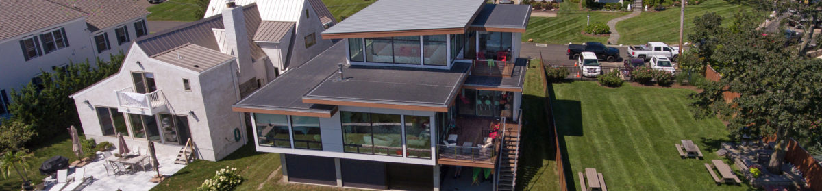
Leaky roof/wall jointRoofing complete, EPDM drip edge in same aluminum material and color used for the main roofCompleted home showing the colors we chose, siding is Pearl Cembonit, corner of the main floor is wrapped in Romantic Walnut Trespa Pura, fascia is Azek in Cypress, main roof and EPDM drip edge is Englert Dove Gray, window trim and garage doors and lower level corrugated aluminum is dark bronze, decks are Cumaru with stainless cable rails, exterior stairs galvanized steel
The metal roof can be quite noisy on hot, windy summer days. Not sure if this is because of an installation problem, or if it is just a metal roof thing. But it is loud enough that it is a little annoying. Also if we get a melt and then a freeze you can get some pretty hefty ice slabs that eventually get cut by the seams and then slide off onto the roof below, with a large bang. Given that the roof below is EPDM over rigid foam the makes me worry about getting a puncture, so when these conditions occur I go up to manage the movement of ice from upper to lower roof. I am not sure if there is a better way or not. Our neighbor has some snow guards on his standing seam roof, perhaps we should look into putting some of those up. There are also some little stick on shark fins that supposedly slice the ice into smaller chunks.
As we went through the process of developing the construction drawings with Turkel we made some changes to window sizes and locations to (a) improve potential airflow through the home, (b) improve privacy, and (c) accommodate limitations of another product line we decided to include in the package. Once the windows were on site and they started to go in we learned about implications of some decisions we had made without knowing we had made the decisions.
In the initial design all three bedrooms had operating windows on only one wall (the master had a tall/skinny window around the corner of the main wall of windows). That did not make sense to us, and the next iteration had two windows either side and adjacent to a corner of one bedroom. The discussion with Turkel was about airflow you get when you blow on a straw while you have your thumb over the other end of the straw. So we added some operating windows and tried to get them on opposite sides of the rooms.
The home is on the water and SSE facing, and most of the south and east sides of the home are glass. The prevailing breeze in the summer is SW, and initially there was no nice way to open up the north side of the home without propping the front door open. So we added some windows to the north side, including a large operating casement adjacent to the front door (more on the front door in another post). We also added a high window to the powder room, over the commode in the master (giving windows on two walls of the master bath, up high for privacy, but adding natural light and operable for airflow), and a couple of small high windows in the mechanical room.
The Marvin Ultimate window package was not an insignificant cost that was not broken out in the Turkel purchase order, and we tried to get some visibility into that cost as we looked at making changes to the window package. This process was slow and difficult, so we started talking to other suppliers to try to get some cost granularity. During those efforts a couple of suppliers suggested that (Marvin) Integrity windows might outperform Marvin Ultimates and also save some money. Ultrex windows are strong, resulting in small rails and so larger openings, and are not susceptible to corrosion, so ideal for water front homes. Turkel had limited experience with this line of windows and it was a process to bring them up to speed of what was possible and what was not possible. Fixed Integrity casements are available in sizes up to 49 sqft, which is about as large a window as I’d want to have. The size of Integrity awnings is limited compared to Ultimates, so under large windows we doubled up Integrity awnings (so more smaller operable windows, which was fine with us and has worked well in practice), and for large awnings and a multi-slide assembly we stayed with Marvin Ultimates. The Integrity were available with wood on the interior, as well as Ultrex (we used the latter for bathrooms and laundry and mechanical rooms). All windows were available with square sticking and the exterior bronze color of Ultimate and Integrity windows is VERY close. I think more factory mulling gets done with the Ultimate windows, for our Integrity windows steel was installed for at least some of the mulling (maybe partially negating some of the cost savings, but again in a salt air environment I think I pick Ultrex over Kynar coated aluminum). The Marvin Ultimate hardware is a little nicer than the Integrity, but the Integrity is still quite OK and you would not really notice much of a difference unless it was side by side. The awning control handles are both metal, but on the Integrity the locking levers look like they are metal but they are plastic (on the all Ultrex they are white plastic).
Largest window in the house on right in master suite, pretty close to 7’x7′, steel bar to mull upper units to lower awning assemblies1″ steel plates used for mulling, awnings below large fixed casements for airflowFull Ultrex Integrity windows in guest bathWood/Ultrex Integrity windows and doorMulti slide assemblyTwo Marvin Ultimate awnings on the left, Integrity fixed casements/polygons to the rightIntegrity on the left, Marvin Ultimate on the right, bronze colors quite a close match
On the stuff we learned about after the windows were on site, that was around jamb extensions and how the window frames were placed in the rough openings. Here is where we started to learn how finishing details could have huge cost implications. For the interior window to wall transitions the plans called for two pieces of trim, one of which was dadoed with the drywall going into the dado. Clearly a ton of work and our construction manager was puzzled by the design. If we were going to bring a jamb extension past the drywall I did not understand why we did not just have jamb extensions built into the windows by Marvin, then bring the drywall up pretty tight and use tear away beads to finish, that would have been a lot less work. The typical finish would be to install a jamb extension bringing the jamb flush with the drywall and then banging some casing around the window. None of these approaches seemed to be very clean to me, clean and minimal was a core tenet of the whole project. So we ended up using drywall for the “jamb extension,” using a tear away bead for finishing at the window jamb and a corner bead at the drywall to drywall corner (much as you would handle the outside corner of a wall). Still a lot of work (and cost), but a much cleaner look.
Window to wall transitionsDrywall jamb extensions, tear away beads at window jambs, corner beads at wall corners
After the windows were in we learned about the importance of how those are placed in the rough openings. The plans called for 1×3 furring of all exterior soffits and interior ceilings. Our construction manager thought it was a waste of time and money to add furring to all of the joists for the ceilings, and installing furring on all of the (pretty extensive) soffits was not going to be cheap. If you did one and not the other the interior to exterior transitions at the windows would have a 3/4″ step from the side with furring to the side without. We decided to skip the furring and deal with gaps that might require trim on the exterior.
During the development of the construction drawings we had been discussing cladding options. On the lower level our thought was to have corrugated break-away aluminum panels between the concrete piers, and we had the idea to bring this aluminum up at a corner of the house to provide an accent to the main cladding (Cembonit cement board panels, more on that in another post). What I did not realize was that as a result of floating the idea of the corrugated aluminum we signed up for 2×4 furring for the cement board rain screen siding. So windows were installed with frames sticking 1.5″ out from the sheathing, so they would be flush. We ended up skipping the idea of the accent corrugated aluminum, instead using Trespa, which would install much as the cement board panels. A 1.5″ rain screen gap seemed crazy to me, though it might have been nice for bird nests. We went with 1x furring, so our window frames project 0.75″ beyond the cladding. Not the end of the world, still looks OK, but during the development of construction drawings I think it would be good if architects highlighted choices being made that have major cost and/or aesthetic implications.
Window frames about 0.75″ proud to siding
Also not sure who picked out the trim for covering the mulls, it wasn’t us, I probably would have picked flat/plain trim. This is what came with the windows, maybe it was a standard/default thing. One of those things that I realized when it was ready to go on and there were bigger battles to fight …
As we were securing our initial (Coastal Area Management, or “CAM”) approvals Turkel was preparing a purchase order that would take us through the detailed design process and the procurement and assembly of a prefabricated “package,” leaving us with a watertight shell, including windows and exterior doors, which we would then finish with a local builder (walls left open for installation of MEP systems, insulation, etc.).
The purchase order included:
Construction and permitting drawings
Permitting support
Shop drawings
Procurement and assembly of the package
Trusses and framing, architectural glulams, etc.
2×6 on 16″ exterior walls
Huber ZIP sheathing (1/2″ exterior walls, 5/8″ roofs)
Warmboard-S subfloors
Marvin Contemporary windows (DP50) and a Marvin Multi-Slide door (DP40)
Local builder identification/vetting/selection
The purchase order did not include:
Foundation (<=0.25″ out of square, elevations within 0.25″)
We had two main concerns with the purchase order, neither of which were show stoppers, but were still concerns:
There was no transparency into costs, for example we had no idea what the window package cost was, or what the markup on same was.
Somewhat related to that, this was a fairly large turnkey project with conveyance to us at completion, so we were being asked to assume a level of credit risk that is unusual in new home construction (where you would normally have a number of payments, with lien releases along the way, so you would never have too much exposure to your builder or a subcontractor). If we had been funding this portion of the project with any debt and the lender was paying attention this probably would have been a problem.
A prior Turkel client we spoke with had contracted directly with the window provider and also with the provider of the building components, which would have addressed both these concerns, but Turkel pushed back hard on this approach. The lack of transparency into costs was particularly frustrating as we started working through the details of the window package, more on that in a bit.
So with the CAM approval behind us the goal now was to get a building permit ASAP, and to get on with the construction. Prior to the CAM approval we had worked through some different options for structural engineering and ended up engaging The DiSalvo Engineering Company directly (rather than through Turkel, which would have added a 20% markup). The DiSalvo contract included the preparation of stamped detailed plans for the foundation and structure of the home and periodic site visits to check conformance to plans.
So on to the process of getting to building department approval of construction drawings:
5/14 – Turkel provided a DD (design development) set of plans to get the structural engineer going and to help with initial efforts to identify and select a local builder.
The DD set was provided to DeSalvo 5/19 and there was back and forth between them and Turkel. DiSalvo provided schematic framing plans to Turkel 6/9 for discussion, and we were all targeting 7/1 for a CD set we could use for the building permit submission. While this was in process we were weighing timber vs helical piles for the foundation system, discussing MEP design vs design/build, and looking more closely at the window package (SD did not give much or any consideration to air flow through the home). We were also working on a Turkel provided “builder specification” that would be used to cost out the non-package portion of the project and select a local builder.
7/1 – DiSalvo provided a foundation permitting set of drawings. At this point engaging a local builder and engaging a pile driving firm were the critical path items, so we elected to wait for a full set of plans and make a single permit submission.
8/3 – Submitted plans for permitting. Norwalk lost the plans and gave them another set a week or so later.
8/22 – Met with planning & zoning to go through their feedback, which was small inconsistencies between different drawings, need to label this and that, etc.
8/29 – Submitted updated drawings for permitting.
9/1 – Planning and zoning pointed out a few small mistakes/inconsistencies.
9/3 – Submitted updated drawings for permitting.
9/13 – Zoning permit issued.
9/15 – Building permit issued. So 13 months from signing contract with architect we had a building permit!
As we got into costing out the non-package part of the project, the main floor deck included about 355′ of steel beams (main floor deck roughly 49’x46′), about 110′ of which were under moment frames. And grade beams were mostly #6 rebar, which is unusual for residential construction. Turkel had another structural engineer that thought the home could be built without any steel, and DiSalvo said they could reduce steel a bit but the downside to that was additional concrete piers and steel to wood connections. Given where we were in the project re-doing the structural work was not an attractive option, and Turkel ended up moving the main floor deck and steel into the package, which was coming from a fabricator in Canada.
Turkel works with several different fabricators, and our purchase order indicated they would be using TekkHaus (no website any more, maybe they were acquired, or went out of business, not sure). For the steel value engineering Turkel worked with Pacific Truss Homes, so they were added to the mix with DiSalvo. The value engineering eventually went nowhere and we ended up back with TekkHaus for fabrication.
10/14 – Received final version of foundation plan with pile locations (as a result of coordination with package fabricator adjustments to the permit set were made).
2/16 – Complete construction set issued. Included additional detailing from the permit set, and incorporated a lot of work on the window package, window locations and sizes, and instead of just Marvin Contemporary went with a combination of Marvin and Integrity, more on that in a separate post.
4/20 – Final update to construction set. I think this was mainly window detailing updates.
Before construction could start we had to secure three main approvals:
Coastal Site Plan
Zoning
Building Department
Norwalk Planning & Zoning handled the first two of these, and we were told that the CAM approval process could take about 60 days, so we wanted to kick that off ASAP. Doing so required plans for the house, but did not require a construction set, and did not even require a final deep foundation design, it was sufficient to indicate the house would be raised and on a deep foundation system. So once the conceptual design was complete on 1/20/16 we kicked off the CAM approval process, and to avoid any potential re-work wanted to have that complete before work on construction drawings for zoning and building department approvals started.
The main takeaway on the CAM application requirements was that we needed to engage a civil engineer to prepare a site plan, and that this was likely the main critical path item. Submissions were due about 3 weeks before the plan review meeting dates, which were generally monthly. In casting around for a local civil engineer a couple of candidates would have taken us at the end of a queue of existing commitments, but Landtech was able and willing to get right into it and pursue an aggressive submission and approval timeline, so they got the gig. They started working (without an agreement in place) on Tuesday 2/16/16 and managed to submit a package on 2/18/16 for a meeting on 3/10/16.
Prior to the 3/10/16 meeting Norwalk Planning came back with some feedback on our submission. Despite our siting the home in the AE flood zone operation of the lot we were told the home had to be built to VE flood zone specifications. We tried pushing back on this, it seemed like it might be a difficult battle to win and we were happy to elevate the home and park under it. The main drawback to the VE rules is that you are not allowed to do more than minor drainage-related grading, whereas in an AE zone you can bring the lot up by 3 feet (which others in our neighborhood have done). Our slab ended up at 7.8′ (1′ above the average lot level), with AE and VE zone base flood levels at 11′ and 14′ respectively. Norwalk Planning also wanted to know more about the foundation, which at this point had not been designed (though we had started to look for a structural engineer, thinking it might be best for the same person to do the foundation and house, rather than using the geotechnical engineer for the foundation and then having him or her coordinate with the structural engineer). We got away with showing some timber piles in the drawings (which were ultimately below grade into grade beams, with concrete columns supporting the house). Finally Norwalk Planning wanted an elevation certificate, architect thought the structural engineer, who had not been engaged, would provide, surveyor wanted construction drawings to provide, and Landtech ultimately provided (with a CT Licensed Professional Engineer seal).
Landtech asked if we wanted to have a catchment area along the edge of the seawall of our lot, with grasses etc., the idea of a barrier between the rear yard and the seawall/water did not appeal to us, so we ended up with a site plan that included 90′ of buried Cultec C-100HD galleries with water shed by driveway and roof piped to same.
At the Plan Review Committee Meeting on 3/10/16 our project was discussed and there was no call for a public hearing, which is apparently something that can be required. Landtech was hoping to secure Zoning approval at the meeting the following week, but prior to that meeting our project had to be reviewed at the next Harbor Management meeting, which meeting I attended, and was unremarkable, on 3/23/16. While this was going on we worked with Turkel and Landtech on a final version of the site plan that brought the lower level slab up a foot from the average lot grade (I really had to fight for this), avoided a variance by making some adjustments to keep the mid-peak of the roof at 31′, and fiddled with siting a bit to comply with neighborhood setback requirements that were more stringent than Norwalk B Residence “height and bulk” limits.
A final submission to Norwalk Planning and Zoning was made 3/24/16. Prior to this submission I ordered a HP Designjet T120, which can print ARCH D (24×36 inch) plans. Printing multiple sets of plans out at Kinkos was costing a small fortune. The Zoning Commission approved the CAM application at its meeting on 4/20/16 with an effective date of 4/29/16. Next step was to get the construction drawings done.
We started talking to Turkel about the project a couple of months before we closed on the lot, and signed a Design Services Agreement (DSA) with them a couple of weeks before closing, with a contingency on closing, but no plan not to close and a desire to hit the ground running. The DSA deliverables included the development of a 3D digital schematic/model, then creation of 2D plans, a written specification with major interior and exterior elements, and pricing for a prefabricated component package.
Prior to launching the design process we were drawn to the Axiom 2340. We liked the open L-shaped living area with the kitchen at the elbow, and the 2-story “light well” surrounding a loft, adding to an open feel and providing light without creating a lot of dead/wasted volume. The issue with the 2340 was that it was only about 31′ wide and our lot was a trapezoid with 75′ on the water and 50′ at the road, so we wanted to push towards the water and go as wide as possible. Ideally we also wanted the master on the main level, and to have water views from that and the main living area. This led us to think that maybe a Turkel design for Lindal, the TD3 2100, might be a better starting point, but we left the starting point as a TBD as there were some things we did not like as much about the TD3 2100 (lots of bedrooms, smaller living area) and Turkel’s pitch was that they were going to ask us questions and make a recommendation.
Here are the major “touch points” and steps of our initial design “program:”
8/3 – Signed the Design Services Agreement
9/2 – Turkel architect made a site visit
9/16 – Online meeting to review a “site packet.” Main thing here was defining the building envelope based on zoning setback and height limitations, and also understanding the flood zone requirements. SketchUp was used for the online meeting.
9/29 – Online meetings scheduled for 10/7, 10/22, and 11/11. We were sent a program worksheet that listed rooms/dimensions/areas/comments, and we returned this worksheet with our comments. 3BR/2.5BA, little over 2500 soft. We nixed the idea of tray ceilings in the master and master bath.
10/6 – Online meeting scheduled for 11/25
10/7 – Online meeting to review program worksheet and discuss high level design, rooms, locations, etc. Looked at some different Turkel designs and discussed the idea of Axiom 2340 with a master sweet stapled to the side of it. Next step selection of a model/design that could be starting point for our home.
10/22 – Online meeting, “Schematic Design Review 1.” Based on our feedback on the program worksheet we were led through a series of progressions with “jelly block” rooms moved around to create a series of 3D bubble diagrams. The final progression was indeed something like the Axiom 2340 with a master suite stapled to the main level. The layout of the main spaces was pretty close to the final result, just needed to sort out location of master bath, closets, mud/laundry and mechanical rooms, and delete an upstairs bedroom. We were tasked with providing feedback in the form of what we liked and what we saw as issues (rather than providing specific solutions) to allow them to digest and refine the design.
10/26 – Received pdf packet from the 10/22 meeting, included 3 schematics, first of these was last progression from our meeting and clearly the basis of the design going forward.
11/1 – Sent our feedback on SD1. Suggested we might prefer closets to be adjacent to master instead of ensuite, discussed need for living room to also be media room, and deleted an upstairs bedroom, making other bedroom larger and maybe giving it a small deck. We went out into a parking lot and blue-taped outlines of the main living spaces to try to get an idea of size and feel, and based on that suggested that we might like a little more living room and a little less deck.
11/11 – Online meeting, “Schematic Design Review 2.” Very close to the final design. Walls were added to the model, which we were told could consume up to 15% of the floor area, and during the meeting we were able to see things moving around the interior of the 3D model.
11/14 – Received SD2 pdf packet from the 11/11 meeting.
11/18 – Sent our feedback on SD2. Didn’t like the idea of transiting the ensuite to get to one of the master suite walk-in closets, and asked about increasing size of master and guest a little bit. Asked how we would go about finding a structural engineer and also signed up geotechnical engineer for soil survey and thinking about who would design the foundation, which would likely be a deep foundation (i.e. piles). Looking forward also visited Norwalk Planning & Zoning to ask about the CAM (Coastal Area Management) approval process, which we were told could take a couple of months and so wanted to be on top of that. They marked up the requirements/forms for us, and one of the requirements I latched on to was a “drainage report.” We asked the geotechnical engineer if that could be added to his scope, but he told us we would need to engage a civil/site engineer for this. We were also wrestling with siting home in A flood zone vs pushing towards the water (where lot is wider) and having some of the home in the V zone, and trying to understand cost implications of this decision. It was very hard to get specific information on the insurance aspect of this decision without elevation certificates, but the guidance seemed to be that siting in the V zone would cost “a lot more” (even if positively elevated).
11/25 – Online meeting, “Schematic Design Review 3.” Pretty much the final design. Spent some time discussing siting in A vs V, with setbacks it would be tight keeping footprint in A (which is what we ultimately did, trimming some things to wedge the home in to the permitted envelope).
12/1 – Received SD3 pdf packet from the 11/25 meeting.
12/4 – Sent our feedback on SD3. Ensuite shower size, vanity configuration, built-ins, WICs. Small stuff. Asked what the next step was.
12/10 – Turkel said they were incorporating our comments and bringing the level of finish up in the model (cladding, windows) so it would look more like a house, and that once we signed off they would send a package out to get pricing for both their package and our local builder (local builder TBD).
12/29 – After pestering Turkel a bit received the “final design packet” (SD4).
1/5 – Sent our feedback on SD4. WICs in master suite, kitchen design (started to realize we might need help with this), concerns about blinds for tall skinny windows, idea of sliding doors from dining room to deck, and started asking questions about windows to promote air flow. On the small powder room, 5×5 near the front door, realized that was small so we needed to be smart about layout, and found a great post on powder rooms (I probably need to create a page with a list of links to sites I found helpful), so we suggested changing from A to B or C.
1/18 – Online meeting, “Schematic Design Review 5.” Mainly discussed ensuite layout, we liked Turkel’s solution to our feedback. They had some concern about commode being visible from the hallway/master, but I viewed that as big positive, with the bathroom and commode doors open there is a water view from the seat! The ensuite ended up at a bit over 140 sqft, not small but also not enormous. A large shower at 5.5x6ft, commode with a pocket door, 8′ vanity, and plenty of room for a tub.
Throne view
Final addition was a largish (12’+) sliding door for the dining room. We like the idea of being able to open up the dining area to the deck/outdoors/view. Turkel suggested sliding over accordion as the former more like big windows when closed, and given climate they would be closed quite a bit. Next steps pricing, assembling the CAM application, and a cabinetry questionnaire. The Turkel team told us we were on track for construction to start in the summer (’16).
1/20 – Received SD5 packet from the 1/18 meeting, also a cabinetry survey and design specification. Still lots of design work left to do before construction drawings would be done, but I would say this concluded the conceptual/schematic design phase of the project. So a little over five months from engagement to completion of this design phase, and we ended up with a 2561 sqft home with 412 sqft of decking (entry, rear, upper) and a lower level garage/storage area of 1725 sqft.
As we started getting into the approval process it became clear the design process was not just about working with the architect. In addition to the architect we needed a geotechnical engineer, a civil engineer, and a structural engineer.
First off was a geotechnical engineer for a geotechnical investigation, some called it a soil survey. Other new homes in the neighborhood had deep foundation systems, so the expectation was that we would need the same. As soon as the old house was demoed GZA GeoEnvironmental came out and took a couple of borings and shortly thereafter provided us with a report that said the topsoil/fill was not capable of supporting a foundation/home, they hit hard stuff at 39-41.5′ below the surface, and that we should use timber or helical piles to support the home.
During the run up to closing on the purchase of our lot in August ’15 we had the idea to build a modern home, roughly 2500 square feet and probably 3 bedrooms and 2.5 baths, comfortable for the two of us, a nice guest bedroom, and a third bedroom for that or for an office or other. When we told the broker selling us the lot about this he suggested we take a look at Turkel Design, who he said designed some nice looking modern homes and offered affordable prefabricated construction. We looked and we liked and were initially drawn to their Axiom 2340 model, which ended up being the starting point for our design.
Big decision though, so we wanted to do our due diligence and explore some other options. We couldn’t find any local architects with experience with modern homes, but heard “I have always wanted to do a modern home” a few times, and while local would have been nice (for design, oversight, local knowledge and relationships) we were not entirely comfortable being a guinea pig. There was a nice looking modern home we could see from our lot that was designed by Maryanne Thompson, similar size to what we were planning, but we tracked down the owner and construction cost of about $2 million scared us away (it did have geothermal and solar panels, but still …). An old high school classmate who is a partner at a small high end firm told us we should plan on $600psf for coastal Connecticut, which still scared us! So this reinforced the idea of modern prefab, we went and met with a Lindal representative, Turkey has partnered with them for some designs in their “TD3 Series,” but we preferred Turkel’s Axiom designs and the idea of stick-built prefab did not resonate. We also popped in to NYC to meet the principals of Resolution 4, we very much liked their body of work. A little “boxier” than Turkel’s designs, perhaps driven by their focus on modular prefab construction. We also looked briefly at Stillwater, and I don’t remember if we looked at them then, but if we were doing this again I might look at them now, evoDOMUS. After boiling the ocean for a bit we landed back with Turkel, we liked their designs, the panelized prefab approach made sense to us, we bought into the timing/quality/predictability rationale for the approach, and they initially suggested a budget that was attractive but that we knew was low, but we thought maybe we could get it done in the same zip code.
The house is not really big enough to have a media room, so the living room also serves as the media room. Two of the three walls floor to ceiling glass with water views, and LOTS of light, one wall with a gas fireplace (Regency U900E, more on that in another post), and fourth side of the “box” open to the kitchen area (L-shaped open layout with kitchen at the corner, dining and living at the legs of the L). Wall with the fire place was about 15′ wide, and wanted a good surround sound set up (5 Meridian DSP speakers), so pretty much the only place to put the TV was over the fireplace, which is not ideal for at least two reasons, it is exposed to heat from the fireplace and it is up higher than it should be for comfortable viewing.
Fireplace heat issue is partially addressed by a 6 inch wide/3cm thick black granite mantel over the fireplace, 5′ above the floor.
Hight issue is partially addressed by a pull-down mount. There were a few options out there, I settled on a manual mount with a recessed box that lets the TV sit pretty flush with the wall when the TV is stowed (and when stowed it can be tilted a little bit, nice for casual viewing when you don’t feel like pulling the TV down). A few people make these things, I got mine from Dynamic Mounting, their Down and Out Recess. It allows you to drop the TV by up to 27″, so stowed the center of our (75″ 90 odd pound) TV is at say 82″, so the mount lets us bring it down to 55″, which is pretty good for sitting on a sofa 15′ away. Mount also lets you tilt the TV, which is nice for viewing from kitchen/kitchen island seating.
I installed the mount myself and it was a bit of a journey. The house package included interior wall framing, and I think maybe I told them what fireplace we were going to use, so they framed up a fireplace column. Issue was that the wall behind the column has master bedroom on the other side, the package assembly crew put plywood for shear wall on bedroom side of studs instead of living room side, as was indicated on the prefab package shop drawings. Plan was for in-the-wall speakers on that wall in the master, and not a great idea to cut big holes in the shear wall sheathing (engineer would have nixed that during an inspection).
Initial fireplace column
So I had them rip the fireplace column out and move the plywood sheathing to the other side of that wall. While I was at it, I created a drawing for the entire wall, would have been an extra from the architect, and saved me having to tell someone else what we wanted to do. Had carpenter reframe the column, this time using VersaLams, so everything would be nice and straight.
Reframed fireplace column
Side note on shear walls, and we had a few of them, I don’t think anyone thought to ask me what side of the walls would be better for sheathing. So if you are building and it isn’t indicated in the drawings make sure you tell your builder where to put shear wall sheathing (i.e., on the other side of walls where you want to put things in the wall).
Box above fireplace, big lag bolts into studs on 16″With mantel and hearth, porcelain fireplace surroundLess speaker grills …
I ran a large conduit from the TV mount box over to the cabinet to the right of the TV, which houses the cable box, surround processor, Apple TV, etc. Using a Harmony Elite so cabinet can stay closed (cable box and other are IR, so line of sight, Harmony hub sits in the cabinet and picks up RF from the remote and then blasts out IR directly and through repeaters).
In the master I just did a flush mount for an old 55″ plasma TV, used a Sanus mount and an Arlington box with power to an outlet in the box and other wires coming up inside the wall.